

How To Change Feature Template And Construction Tool
This tutorial is one of a series that demonstrates best practices for editing in ArcGIS for Desktop. Information technology introduces feature templates and shows how they are created, updated, and applied.
ArcGIS ten.10 for Desktop uses feature templates to create and update spatial data. These templates aid manage symbology and populate selected attributes efficiently. Characteristic templates are usually created in or just before an editing session and often utilize predefined layer symbology displayed in the map's table of contents (TOC).
Feature templates define information used to create a feature, including the default construction tool, selected attributes, and storage rules. Templates contain a user-defined name, description, and useful tags. In one case created, templates are stored in the ArcMap certificate and in an item's layer file.
Well-Behaved Feature Templates
Users often inquire me to explain why feature templates tend to behave badly for them. Carefully constructed and managed feature templates behave quite well, but you need to understand the rules for using them.
The get-go step when creating a characteristic template commonly involves starting an edit session and loading the Create Features window. Often, the editing layer does not announced in the Create Features window, which creates confusion. A template might not announced because
- The layer or its grouping is not visible.
- The layer'south visible scale range is beyond the map's current calibration.
- The layer is a parcel material dataset.
- The layer has a definition query applied, and the default characteristic template does not lucifer that query. This is the most mutual reason.
The all-time way to avoid problems with templates is to create the definition query outset, clear whatever old templates, and create a new template for the queried data.
Getting Started
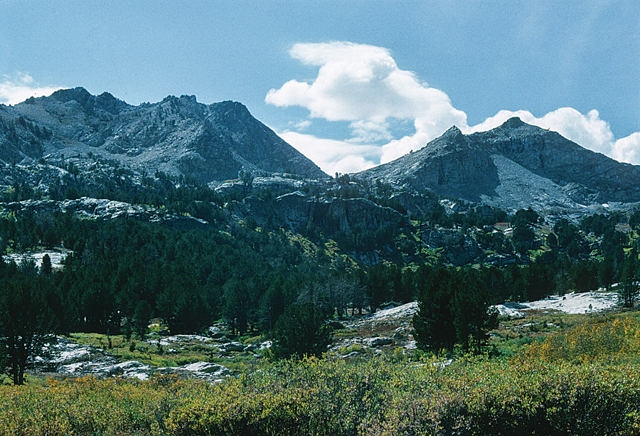
This practice uses data shown on the US Geological Survey Antler Acme 7.5-minute quadrangle. This is a portion of the Battle Mountain, Nevada, training fix that has been used in vii previous exercises. This installment in the series will explain how to create, update, manage, and use characteristic templates for geological and topographic data including faults, hydrology, mineral occurrences, and bedrock.
To go started, download the sample dataset[Naught] and unzip information technology to a local automobile.
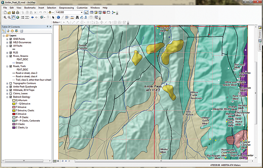
- Offset ArcMap, navigate to the \Battle_Mountain08 binder, and open Antler_Peak_01.mxd.
- Explore the data layers and wait at their attribute tables. Expand all layers and turn them on and off. Check out labeling schemes. Verify that the Maplex label engine is being used by right-clicking the data frame, choosing Properties, and clicking the General tab. Under Label Engine, make certain Maplex is selected. Maplex comes with ArcGIS ten.3 for Desktop.
- From the ArcMap standard menu, cull File > Map Certificate Properties. Consummate the descriptive fields, providing a title, summary, and simple description. Include your name equally Author and include Antler Height, Geology as tags. Set paths to relative and set Battle_Mountain08\GDBFiles\Antler Peak.gdb equally the default database.
This file geodatabase contains all the data for this exercise except for one georeferenced image, which is stored in Battle_Mountain08\JPGFiles. Since this is a rather simple editing exercise, information technology uses only i geodatabase to store all vector information. In an ArcMap editing session, only shapefiles stored in a common folder or feature classes inside a selected geodatabase may be edited.
Sometimes, when I edit in large, complex projects or share editing duties with others, I store edited data in one or more separate geodatabases to minimize the chances that a data direction disaster might occur. In one case editing is finished, I may copy edited feature classes back to master project geodatabases. Nevertheless, for this exercise, remember to brand just the editing layer selectable.
Preparing Data Layers
Begin by studying all the layers in the map.
- Correct-click the Bedrock Geology layer and cull Information > View Item Description to view the attribution. It is limited but is a complete attribution.
- Open the attribute tabular array for All Faults and sort on the [F_TYPE] field in ascending order. Notice that attributes include Faults – Certain, Faults – Concealed, Faults – Inferred, and Thrust Fault – Certain. Close the All Faults attribute table.
- In the TOC, correct-click All Faults and select Copy. Right-click the data frame proper noun, Layers, and choose Paste Layers twice. Select all three instances of All Faults and group them, naming the group Faults Grouping. Rename the first copy "All Faults to Thrust Faults" and the second re-create "Normal Faults." Go out the All Faults layer unchanged and turn it off.
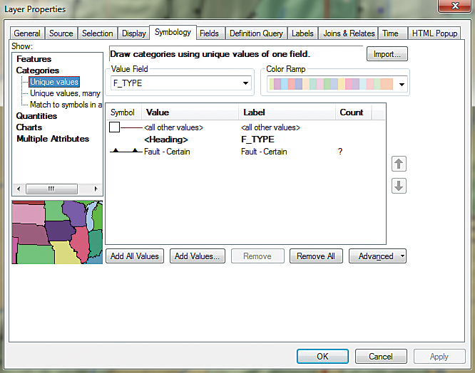
- Double-click Thrusts, select Backdrop and click the Definition Query tab. Utilise the Query Architect to create the expression F_TYPE = 'Thrust Fault-Certain'. Select and re-create this query to your clipboard. Then click OK and Apply.
- To symbolize the Thrust Faults layer, double-click the layer, choose Properties, and click the Symbology tab. Set Categories to Unique Values and the Value Field to F_TYPE. Click the Become All Values button, uncheck , and double-click the default symbol.
- In the search window, blazon "thrust fault certain," select All Styles, and click Search. Six symbols should appear. Select Thrust Mistake, 1st generation-Certain. Click OK twice to apply this symbology. Advisedly inspect the symbology.
- Save the project.
These symbols are included in the Geology 24K Style. They are carefully created to conform with the geology symbol sets used past the US Geological Survey and other agencies. The full symbol definition can be downloaded from the U.s. Geological Survey as FGDC Document Number FGDC-STD-013-2006.
Check Symbol Direction
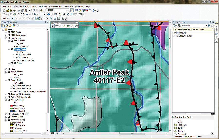
Consider what happens when faulted blocks frequently override other blocks at a depression bending. Symbolized as triangles (or barbs), these symbols should point in the direction that the overlying rocks came from. The next step is to load a map to see if they are correct.
Navigate to \Battle_Mountain08\JPGFiles and load Thrust_Fault.jpg. Zoom in to the northeast corner of the project at a scale of approximately 1:15,000 and inspect the paradigm and the symbolized lines. Notice that the red triangles in the epitome point westward, toward the source of possible compressive forces.
In this case, the Pumpernickel Formation occurs higher up the Antler sequence, and the thrust barbs must be switched. To do this will require opening an editing session, creating a characteristic template, selecting the offending fault lines, and flipping them.
Creating Thrust Mistake Template
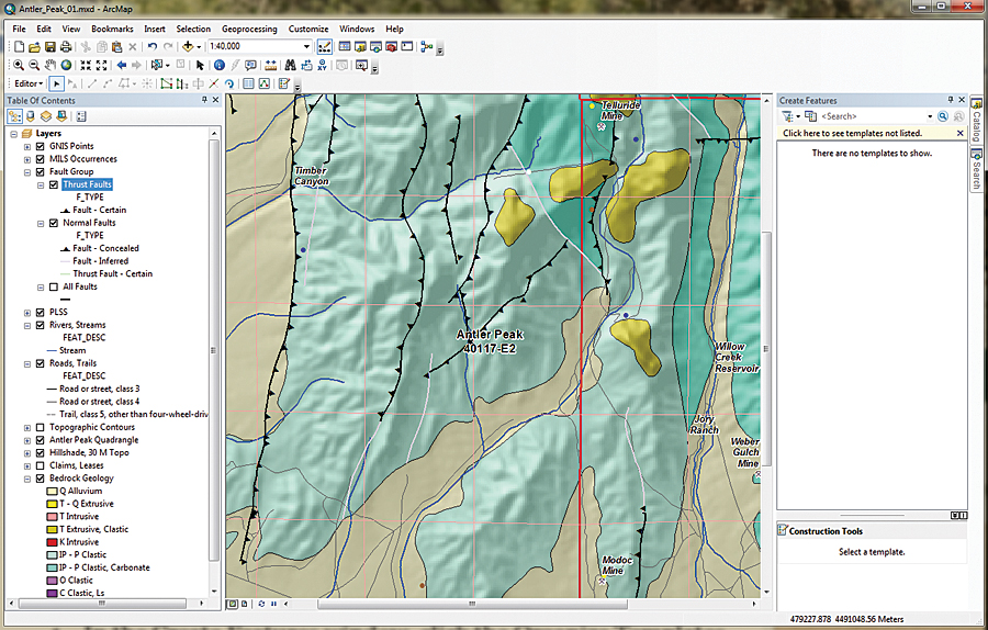
- Before opening an edit session, change the TOC display to List By Choice. Brand Thrust Faults the only selectable layer. Modify the TOC to Listing Past Drawing Order and make sure Thrust Faults is displayed.
- In the TOC, right-click the Thrust Faults layer and select Edit Features. The context carte provides three choices: Commencement Editing, Define New Types of Features, and Organize Feature Templates. The Define New Types of Features option allows symbology editing to be expanded after. Choose Beginning Editing from the context carte du jour. The Editor toolbar should announced and can be docked above the TOC.
- In the Editor toolbar drop-downwards, cull Editing Windows > Create Features. The Create Features window appears and tin can exist docked on the right side of the workspace.
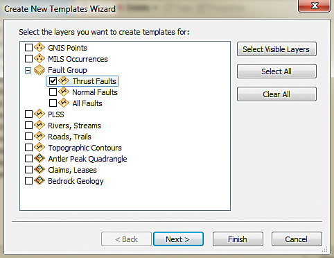
- In the Create Features window, click the Organize Templates button. Inspect the layers listed in the Organize Features Template window. Select Thrust Faults Layer and click the New Template button.
- The Create New Templates Wizard opens. Look at the layers in the Faults Group. Check Thrust Faults and make sure all others are unchecked. Click Next. Click Finish and Close.
- Double-click the new Thrust Fault – Certain template to look at its properties. Inspect the Template Properties. In this dialog box, you can rename the template, specify an alternate Default Tool, and set up field defaults.
- Change F_CODE to 5, F_MOVE to D, and EditCode to 0. At present, when a new thrust fault is created using this template, the attributes will be populated using these values. Click OK.
Flipping Faults
- Open up the Thrust Faults attribute table. Select F_Index = 88, close the table, and look for the highlighted selection in the northeast portion of the map.
- Select the Edit Tool in the Edit toolbar. Double left-click the highlighted segment to display its vertices. Discover the single ruby-red node that marks the terminus of the fault line. Right-click the northernmost vertex and choose Flip. The barbs on the error line change management from e to west. Select the next line (F_Index = 89), and utilise the same process to flip information technology. Repeat the edits for F_Index = 96.
- Inspect your edits, and if they are right, open the aspect tabular array and use the Field Calculator to modify all EditCodes to three.
- Turn on Bedrock Geology labels and use the Identify tool to check the relationships betwixt upper and lower rocks separated by each Fault. Are in that location older rocks on top of younger rocks?
- Open the Edit toolbar drib-down and choose Save Edits. Shut the Thrust Faults aspect tabular array, plough off Thrust_Faults.jpg, zoom to the projection extent, and salvage the project.
Symbolizing Normal Faults
The same steps used with Thrust Faults will exist used to symbolize the Normal Faults layer. The fault lines in Normal Faults will non be edited.
- In the TOC, right-click Normal Faults and open Properties. Click the Definition Query tab. Utilise the Query Architect to form the expression F_TYPE <> 'Thrust Fault – Certain' and apply it.
- Click the Symbology tab. Choose Categories > Unique values, choose F_TYPE as the Value Field, and click the Add together All Values push button.
- Use the search function in the Symbol Selector using the layer name to locate the appropriate symbology from the Geology 24K Manner Reference. For instance, search on fault inferred to find the symbol for the Error – Inferred layer.
- Now create a feature template for Normal Faults. In the Create Features window, click Organize Templates and select Normal Faults. Click New Template, making sure only Normal Faults is checked, click Next and so click Finish. Shut the Template Organizer.
- Salve the Thrust Faults and Normal Faults as layer files to capture the associated feature templates. Save the map.
When finished, audit the mistake symbology on the map. Can you determine the difference betwixt a concealed fault and an inferred fault? A concealed fault is hidden by an overlying geologic map unit, water, or ice, even though information technology may exist observed nearby. An inferred fault's location must be inferred by indirect means such as geophysics and remote sensing.
Summary
This exercise showed how to access meaningful geologic symbology and use definition queries when applying symbology. This updated symbology was used when creating several feature templates.
Acknowledgments
Once once more, thanks to my Boxing Mountain data providers and to my earth sciences followers. Special thanks to my editor, who keeps me always heading in the correct direction.
See also the accompanying article, "Building Antler Meridian."

How To Change Feature Template And Construction Tool,
Source: https://www.esri.com/about/newsroom/arcuser/editing-with-feature-templates/
Posted by: smithmisho1978.blogspot.com
0 Response to "How To Change Feature Template And Construction Tool"
Post a Comment